 Having purchased my first Raspberry Pi a couple of years ago now I've still not got round to implementing some Internet of Things (IoT). The trouble was that I wasn't really convinced it was suitable for the job as I wanted something able to be battery operated to work in remote situations as the power draw was just too great.
I liked the idea of the Arduino stuff but it was as expensive as RaspberryPis once you've hooked it up with wifi and the like.
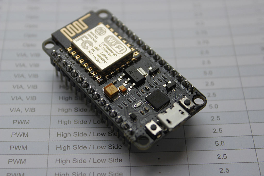
A couple of weeks ago I stumbled across the awesome ESP8266 boards - just what I was looking for. Small, inexpensive and had wifi and an antenna built in. When I say inexpensive I really do mean it you can get going for just a couple of quid.
For my first foray into the scene I opted for a NodeMCU v1.0 development board as it has a USB connection for uploading firmware and power and if you buy a slim one you can connect it to a breadboard for prototyping.
I already own the CamJam EduKit 2 - Sensors lying around as I hadn't yet got round to hooking it up the Pi but I wanted to try it out on the ESP8266-12E. Trouble is there doesn't seem to be any decent instructions on the internet of how to hook up the light dependant resistor. After a bit of scratching around I found out the required resistor (10k ohm) and a circuit diagram from here and I was away.
What you need
List of parts required:
- ESP8266
- LDR / photoresistor
- 10k ohm resistor
- breadboard
- computer with Arduino IDE with ESP8266 library installed
- USB cable
- Male-Male Dupont/breadboard wires
Circuit Diagram
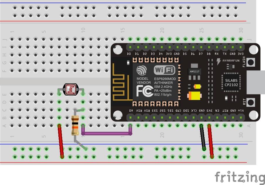
The LDR actually has a an analogue output so it gets connected to the A0 pin. Quite simple really, just wire your prototype up like this:

The code
Simple really, we will just use the example code in the Arduino IDE - go to
File/Examples/1.0Basics/ReadAnalogueVoltage
// the setup routine runs once when you press reset:
void setup() {
  // initialize serial communication at 9600 bits per second:
  Serial.begin(9600);
}

// the loop routine runs over and over again forever:
void loop() {
  // read the input on analog pin 0:
  int sensorValue = analogRead(A0);
  // Convert the analog reading (which goes from 0 - 1023) to a voltage (0 - 5V):
  float voltage = sensorValue * (5.0 / 1023.0);
  // print out the value you read:
  Serial.println(voltage);
}
The output
All we need to do next is to fire up the serial monitor, select 9600 baud and watch away:
2.16
2.13
2.09
2.07
2.06
2.04
2.03
2.02
2.01
2.00
2.03
2.09
2.15
2.18
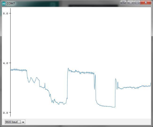
You can also use the serial plotter to see a graph of your results:

Next...
You are then ready to integrate it into your own project.